
Introduction
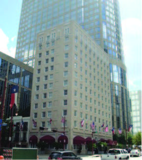 The historic Lancaster Houston Hotel, located in Houston, TX, is a twelve-story structure built in 1926. Originally known as “The Auditorium Hotel,” the Lancaster was designated a Recorded Texas Historic Landmark by the Texas Historical Commission (THC) in 1984. The hotel was also accepted into the Historic Hotels of America Program of the National Trust for Historic Preservation, representing the Jazz Age, in 2010.
The structure is a reinforced concrete frame with clay tile in-fill, single wythe brick veneer, and cast stone trim. The clay-brick masonry exterior wall extends the full building height with aluminum-framed windows that were replaced as a part of a 1982 renovation. Ornamental cast stone elements accent the top and bottom floors and a cast stone parapet cap extends the length of the south and west building elevations. The east and north building elevations consist entirely of the clay-brick, aluminum windows, and terra cotta parapet caps.
The footprint of the building is approximately 100 ft (30.5 m) in the east-west direction and 51 ft (15.5 m) in the north-south direction, for an area of approximately 5100 sf (474 sq m).
Condition Assessment
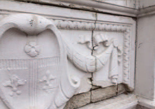
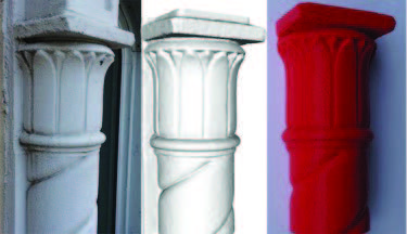
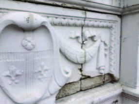 A series of evaluations were performed between 2002 and 2014 to assess the condition of the façade. The evaluations included a binocular survey from the ground and adjacent structures, close-up observation from suspended scaffolding, and laboratory analysis of selected exterior wall materials. The most significant deterioration occurred on the top level of the structure on the south and west elevations. Typical observations included cracks at the spiral columns and mortar joints, localized surface spalling of cast stone trim and spandrel panels, and missing ornamental cast stone spiral columns and brackets
The deterioration was determined to be a result of the lack of adequate cover of the cast stone reinforcement as well as water infiltration into the exterior wall which resulted in corrosion of the façade anchors.
Based on our conclusions, we recommended:
- Sealing façade cracks greater than 0.012 in (0.3 mm) in width
- Repairing localized cast stone and masonry spalls in the facade
- Removing deteriorated cast stone units and replacing them in kind.
The cast stone replacement encompassed a total of 28 column and bracket units and 14 spandrel panels.
Restoration Plan
Original construction documents were not available for this building and made the cast stone replacement even more difficult. Without any details, our only option was to make a mold out of the physical cast-stone ornaments.
We proposed two methods to the contractor to create the molds:
- First, the conventional approach which required vertical access to the façade, removal of a good condition spandrel panel, column, and bracket, and finally, manufacturing of the molds. This method, although tried and true, is costly and comes with the inherent risk of damaging the delicate cast stone features.
- The second method proposed was to use 3D scanning and modeling technology to create a three-dimensional model of the architectural features and use the model to create a negative mold or a master copy. This method removes the risk of damaging a cast-stone piece in good condition.
Given that the contractor had already mobilized on site, a combination of both methods was selected to manage risk and costs. This involved manufacturing molds out of physical spiral column and bracket samples (due to their small size), and creating non-traditional molds from 3D models for the delicate 60 in x 22 in (1524 mm x 559 mm) spandrel panels.
The initial plan was to use our small unmanned aircraft system (sUAS) to document and scan the spandrel panel, a process known as remote monitoring. However, our FAA Section 333 exemption was not approved in time to meet the project schedule. Instead, we utilized the suspended scaffolding already in place by the contractor. Performing the work on a scaffold required a method that was portable and light. Traditionally, laser scanning equipment is heavy, requires a fixed location to scan an area, and requires a clear line of sight. Furthermore, while portable laser scanners exist, they are limited in range and typically require being up-close to the object. For these reasons, we decided to use a low cost, portable, and effective modeling method known as photogrammetry.
Introduction to Photogrammetry
Photogrammetry has been around since the creation of modern photography. In fact, photogrammetry is widely used today in film post-production, forensic investigation, commercial mapping, and even in the construction industry to document construction progress and coordination as well as perform soil volume estimates during surveying. Photogrammetry is the science of making measurements from photographs. In short, computer algorithms attempt to identify points in common between a set of photographs and plot them in a three-dimensional space (i.e. a point cloud). Once the point cloud is created, a mesh which connects all the individual points with flat planes can be generated using traditional modeling software. A 3D mesh allows an engineer to manipulate its dimensions and shapes, analyze the object for stresses and strains, 3D print the model, or use a computer numerically controlled (CNC) mill to create our shape.
Just like every technology, there are advantages and disadvantages to using photogrammetry. The main disadvantage is that the resulting model will not be dimensioned or as accurate as laser scanning. Instead, the resulting point cloud will be a proportioned, dimension-free model that can be scaled to its actual dimensions during post-processing. Additionally, the density of the point cloud (i.e. how much detail your model will have) is largely dependent on the resolution and focus of the photograph, the distance to the object, the available lighting, and the amount of photograph overlap. The advantages are that this method is extremely portable and only requires a camera and a trained photographer and computer modeler. Understanding how these factors affect a particular project can help determine if photogrammetry is the correct approach.
Developing the 3D Models
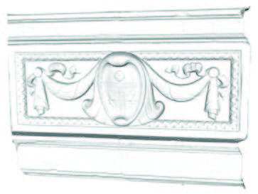
 The general procedure was as follows: While on the suspended scaffold, hundreds of photographs were taken of the spandrel panels, columns, and brackets using indicator targets in the objects so the photogrammetry software is able to recognize similarities between photographs. The photographs were then manually sorted to delete photographs that were either blurry or not part of the data set needed. Once sorted, the photographs were uploaded to a commercially available photogrammetry software package to process the point cloud. Once processed, the point cloud was imported to a free and open-source 3D modeling software in order to create a solid surface mesh that connects all of the points in the point cloud. The time it takes to process a mesh is highly dependent on the complexity of the geometry and the density of the point cloud. For reference, the decorative spandrel took approximately three hours to generate the point cloud, one hour to mesh, and three hours to edit the model and complete the final touches.
As a trial, we used 3D printing to determine if the models were detailed enough for full scale production. A partial model of the spiral column and capitol was generated, edited, and printed using a MakerBot 3D printer and biodegradable thermoplastic aliphatic polyester filament, commonly known as PLA. The result was a miniature version of the column with all its surface defects and details (Fig. 6). Pleased with the results, it was time to move forward with the full scale replica of the spandrel panel.
Design of Cast Stone Spandrel Panels
Matching the existing features of the existing spandrel panels required using cast stone as our final product. Cast stone, as defined by the Cast Stone Institute, is a refined architectural concrete building unit manufactured to simulate natural cut stone. The materials and processes used in the manufacturing of the stone depend on the required appearance and physical properties. Our specifications required producing cast stone with a minimum 28 day compressive strength of 6500 psi (44.8 MPa), a 28 day absorption rate ranging between 6 to 8% and shrinkage not to exceed 0.065%. Additionally, the cast stone was to be reinforced using either non-corrosive reinforcement or welded wire fabric with a minimum reinforcement of 0.25% of cross sectional area.
For aesthetics, the exposed surface of the cast stone needed a fine grained texture similar to natural stone with no obvious air voids under direct daylight at a 5 ft (1.5 m) distance, and of similar color and hue. A silane sealer was specified as a water repellent, and to minimize chloride ion penetration into the substrate material. The existing cast stone spandrel panels are supported by a steel shelf angle connected to the building frame with post-installed anchors spaced at approximately 24 in (610 mm) on-center and are laterally supported by corrugated metal ties spaces at approximately 14 in (356 mm) on-center. For the replacement panels, we utilized the same steel shelf angle to support the gravity loads and secured each panel with four new stainless steel post-installed chemical anchors to resist lateral wind loads. The chemical anchors were detailed to be installed at an angle of 15 degrees from the horizontal plane to provide a mechanical interlock between the anchor and the cast stone spandrel such that the anchor connections do not rely on chemical adhesion only.
Fabricating the Spandrel Panels
 Rapid prototyping, 3D printing, and computer-aided manufacturing were considered to produce the spandrel panel. Immediately, we realized that although advanced, today’s technology comes at a high cost and is limited for size. For instance, both rapid prototyping and 3D printing are limited to objects in the scale of 1 cf (0.03 cm), more or less, and can cost several thousand dollars. Traditional computer-aided manufacturing allowed us to manufacture larger sized objects, at a fraction of the cost, using various different materials (wood, stone, metal, and foam).
Several options were considered to fabricate the spandrel panels.
- The first option was to CNC high-density foam to form the shape, which would then be coated with polyurethane and a mortar slurry mix to match the existing conditions.
- The second option was to CNC low-density foam to form the shape, create a rubber mold, and then use cast stone to create the spandrel.
The second option was chosen due to lower costs, ability for the contractor to cast their own units, and the improved durability provided by cast stone over polyurethane-coated high density foam.
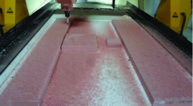
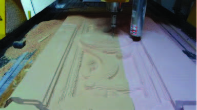
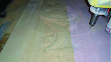
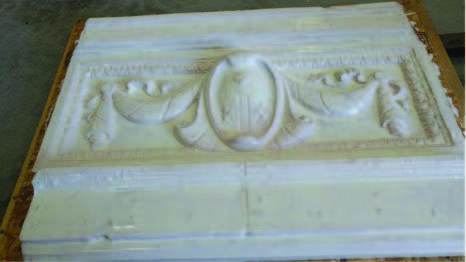
A Stereo Lithography (STL) file was exported and sent to the manufacturer. This file format is widely used for rapid prototyping, 3D printing, and computer-aided manufacturing. Using a three axis CNC machine, a foam master copy of the spandrel panel was milled and sanded. The final master copy coated with polyurethane was delivered to the project site ready for the mold-making process.
Conclusion
 The spandrel panels are currently being cast using a mold created from the foam panel and will be installed thereafter. Based on this project experience, we are confident that photogrammetry can be implemented in any project requiring replacement of ornate or historical building features without the risk of damaging the existing conditions of the facade and at the same time, reducing design and construction costs.
For more information about this project and much more reach out to our experts today!
 Al Bustamante located in Walker’s Houston office
 Diego F. Romero located in Walker’s Chicago office